Posts

Showing posts with the label test

INT0_INTERRUPT_EDGE_DETECTION_TEST_18f4550

        Led changes it's state whenever there is rising edge at RB0.  // Int0 Test  //Input at RB0 #define led PORTb.f1 sbit LCD_RS at RB2_bit; sbit LCD_EN at RB3_bit; sbit LCD_D4 at RB4_bit; sbit LCD_D5 at RB5_bit; sbit LCD_D6 at RB6_bit; sbit LCD_D7 at RB7_bit; sbit LCD_RS_Direction at TRISB2_bit; sbit LCD_EN_Direction at TRISB3_bit; sbit LCD_D4_Direction at TRISB4_bit; sbit LCD_D5_Direction at TRISB5_bit; sbit LCD_D6_Direction at TRISB6_bit; sbit LCD_D7_Direction at TRISB7_bit; // End LCD module connections  char txt1[] = "INT0_RISING_EDGES";  char str[12],lcd[12],i,j;  int cnt;   void main()      {       OSCCON=0xff;       TRISB=0x01;       ADCON1 = 0x0F;       CMCON = 0x07;       INTCON2.INTEDG0=1; //interrupt on rising edge       INTCON.GIE=1;       INTCON.INT0IE=1;  ...
INTERRUPT_ON_CHANGE_18f4550

Image
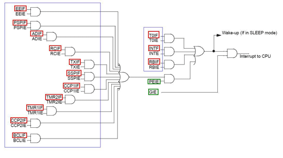
//interrupt  on change //PORTB pin to 7 IOC is used  as interrupt source // any change on RB4 to RB7 //would drive pic to interrupt  and led lit    #define led PORTC.f1 void main()            {            TRISC=0;           // output            TRISB=0xf0;         //RB4 to RB7 as input            ADCON1=0x0f;       // all port digital            INTCON.RBIE=1;      //Enable portb Interrupt on chaner            INTCON.RBIF=0;      // clear interrupt flag             INTCON.GIE=1;            for(;;)            {             }     ...

MOSFET_STEPPER_MOTOR _DRIVER

Image
one mosfet (1rfz44n) and one 10k resistor is used to switch one phase of 28BYJ-48 stepper motor. 

stepper_28BY_and_with_driver_and-pic18f4550

Image
Delay time is required and stpper would not move when the pulses are too fast. Each winding consume nearly 700mA and  Under half stepping it is about 1400mA. I test with 7805 1A regulator. //stepper test void main()      {    OSCCON=0xff;   //osc configuration for max speed of internal                              osc      TRISA=0;           for(;;)              {               // 8 steps for helf stepping               // 4 steps for full stepping                             PORTA=0x0E; //1110               delay_ms(5);           //    PORTA=0x0C; //1100     ...

SG90 SERVO TEST WITH 18f4550 (Bread Board)

Image
The code. . . . .  #define servo PORTA.f1  unsigned int i;  void ccw()             {             servo=1;             delay_us(1000);             servo=0;             delay_us(19000);             }             void mid()             {             servo=1;             delay_us(1500);             servo=0;             delay_us(18500);             }   void cw()             {             servo=1;             delay_us(2000);             se...

PIC 18f4550 SERVO TEST WITH PROTEUS

pin and frequency is my common mistake. mikro c  codes. . . . . . . .  #define servo PORTA.f1  void ccw()             {             servo=1;             delay_us(1000);             servo=0;             delay_us(19000);             }             void mid()             {             servo=1;             delay_us(1500);             servo=0;             delay_us(18500);             }   void cw()             {             servo=1;             delay_us(2000);   ...

PWM_ADC_LCD_WITH_18f4550

  // pwm with lcd   //working   // Be sure RW pin to connect to ground unsigned long  i,j,Adc_Res,pwm; unsigned char op[12],lcd[12]; char *text = "PWM AT 5kHZ"; char *text1= "DUTY ="; char *text2="%"; void main()      {      k=234;      TRISB=0;      ADCON1=0x0E;      PORTB=0;      TRISA.f0=1;      TrISC.f2=0;      PWM1_Init(5000);      PWM1_Start();       Lcd_Init(&PORTB);       Lcd_Cmd(Lcd_CLEAR);       LCD_CURSOR_OFF;       Lcd_Out(1, 3,text);       Lcd_Out(2,1,text1);       Lcd_Out(2,12,text2);       PWM1_Init(5000);       PWM1_Start();      for(;;)       {        Adc_Res=Adc_Read(0);       Adc_Res=(Adc_R...

TIMER0 interrupt part 1

internal osc 8Mhz ကိုသံုးျပီးတြက္ထားပါတယ္။ timer ထဲကိုသြင္းတဲ့ ခုန္လွိဳင္းကို clock source ကေနယူလို႕ရသလို ျပင္ပကေနေပးလို႔လဲရပါတယ္။ TIMER 0 က 8 bit (TMR0L) နဲ႕ 16bit (TMR0L + TMR0H) ႏွစ္မ်ိဳးရွိရာမွာ 8 bit (TMR0L) ကိုပဲသံုးပါမယ္။ instruction တစ္ခုျပီးဖို႔ 4 cycle ၾကာပါတယ္. . . . Tosc ရဲ့ ၄ ဆၾကာခ်ိန္= 4 x(1/F0sc) =4/8e6=0.5e-6 sec Timer0 က 0.5e-6 sec (timer period) ၾကာတိုင္း ၁ တိုးသြားတယ္း. . . . ေနာက္ဆံုး  8bit တန္ဖိုးျပည့္သြားတဲ့ အခါ ( 1111  1111 ) timer0 overflow ျဖစ္တယ္.. . Timer0  ကို မ၀င္ခင္ ခုန္လွိဳင္းေတြကို prescaler ကိုျဖတ္ခိုင္းျပီး  အခ်ိန္္ၾကာၾကာေရႏိုင္ေအာင္လုပ္လို႔ရပါတယ္။ TMR0L ဆိုတာက TIMER0 8 bit mode မွာ ေရတြက္မွဳကိုမွတ္တဲ့ register ပါ။ TMR0L ကို ၁၀၀ ထားလိုက္ရင္ (256-100=156) timer overflow ျဖစ္ဖို႔ 156 ခ်က္ ေရရမွာေပါ့။ PRESCALER ကိုမသံုးဘူးဆိုရင္ .. . prescaler တန္ဖိုး ကို 1 လို႔ယူဆပါမယ္။ Overflow time = 4 x TOSC  x Prescaler x (256 - TMR0L) =0.5 e -6 x 1 x 156 =78 e -6 second  78 e -6 second   ၾကာရင္...

ADC_WITH_3_DIGIT_DISPLAY_18f4550

 //all port test  // SURE TO CHECK LVP OFF //POETD.b0 to a //..... //..... //PORTD.b6 to g #define dig1 PORTD.f5 #define dig10 PORTD.f6 #define dig100 PORTD.f7  unsigned int show=0; unsigned char num1,num10,num100,cnt; unsigned char pattern;     unsigned char display(unsigned char num)     {     unsigned char dig[]={0x3F,0x06,0x5B,0x4F,0x66,0x6D,      0x7D,0x07,0x7F,0x6F};      pattern=dig[num];      return(~pattern);      }  void interrupt()  {                 TMR0l=250;     //2.5ms interrupt                 INTCON=0x20;   //check                 portd=0;     if(show==1)     {             PORTB=display(num1);           ...

4550_timer_interrupt_and_3_7_segments_display

 Avoid using too long interrupt time. In my case, LEDs do not glow equally and I got best result at TMROL 250. The next thing is I could not watch the INTCON register in mikroc debugging. Remember that I am just testing and a good one at PIC. //POETD.b0 to a //..... //..... //PORTD.b6 to g #define dig1 PORTD.f5 #define dig10 PORTD.f6 #define dig100 PORTD.f7  unsigned int show=0; unsigned char num1,num10,num100,cnt; unsigned char pattern;     unsigned char display(unsigned char num)     {     unsigned char dig[]={0x3F,0x06,0x5B,0x4F,0x66,0x6D,      0x7D,0x07,0x7F,0x6F};      pattern=dig[num];      return(~pattern);      }  void interrupt()  {                 TMR0l=245;     //2.5ms interrupt                 INTCON=0x20;...

18f4550_timer0_interrupt_test

//source: mikroelectronica's example  // working code  //disable lvp_off //blink led on portb and portd unsigned cnt; void interrupt() {   cnt++;               // Increment value of cnt on every interrupt   TMR0L  = 96;   INTCON = 0x20;       // Set T0IE, clear T0IF }//~ void main() {   TRISD=0;   ADCON1 = 0x3F;        // Set AN pins to Digital I/O   T0CON  = 0xC4;        // Set TMR0 in 8bit mode, assign prescaler to TMR0   TRISB  = 0;           // PORTB is output   PORTB  = 0xFF;        // Initialize PORTB   TMR0L  = 96;          // Timer0 initial value   INTCON = 0xA0;        // Enable TMRO interrupt   cnt = 0;              // Initialize cnt ...
coded by me, Nai Lin 'finished 676 solar charging controller 'mcu will sense the battery charging state and 'automatically turn off when the battery is fully charged. 'And check the charging state after full charge mode and connect 'the battery to solar automatically 'rc1 to rc4 for charging indicator 'ra0 for vtg sensing at battery terminal ' 'battery sensor decimal read out '10.8 2.7 553 '11.6 2.9 594 '12.4 3.1 635 '13.2 3.3 675 '14 3.5 717 'used registers 'TRISA 'TRISC 'PORTA 'PORTC 'ADCON0 'ADcon1 'ANSEL 'ADRESL 'ADRESH 'RESS WORD SIZE VAR TRISA=000001 'RA0 is analog input TRISC=000000 'PORTC is OUTPUT ANSEL=000001 'AN0 channel 0 is selected RESS var ...

16f676 solar charger

Image
I coded for my own solar charging controller and it is now working well. This version does not detect solar output. Knowing only the appearing voltage at battery terminal. Coded by me, waagyi 'finished 676 solar charging controller 'mcu will sense the battery charging state and 'automatically turn off when the battery is fully charged. 'And check the charging state after full charge mode and connect 'the battery to solar automatically 'rc1 to rc4 for charging indicator 'ra0 for vtg sensing at battery terminal ' 'battery sensor decimal read out '10.8 2.7 553 '11.6 2.9 594 '12.4 3.1 635 '13.2 3.3 675 '14 3.5 717 'used registers 'TRISA 'TRISC 'PORTA 'PORTC 'ADCON0 'ADcon1 'ANSEL 'ADRESL 'ADRESH ...